What it shows:
A device to measure distances to an accuracy of fractions of the wavelength of light, it also provided the critical experiment for the non-existence of the ether and for the constancy of the speed of light in all inertial frames.

How it works:
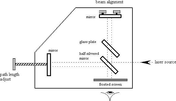
A light source (these days a laser or LED with beam expander) has its beam split onto two perpendicular paths by a half silvered mirror (figure 1). Both beams are reflected back by mirrors to recombine.

Historically, the most notable use of the Michelson interferometer was an experiment preformed by Michelson and Edward Morley in 1887 to measure the absolute velocity of the Earth through the ether. The measurement of light travel time along each arm of the interferometer would depend on the vector sum of the velocity of the Earth through the ether and the velocity of light. One arm of the interferometer is aligned parallel to the motion of the earth through space (and therefore the ether), so the second arm is perpendicular to the motion. The equations for travel time are given in many books, 1 with the result that the parallel arm travel time is less than the perpendicular arm by
![]()
or about half a fringe shift in the interference pattern. By rotating the apparatus 90°, the observer should see the fringes shift on the screen. What was observed was no change at all. The two consequences for this null result were an ether with no measurable quantities whatsoever and a speed of light constant in all reference frames, the fundamental postulate of special relativity.
figure 1. interferometer layout

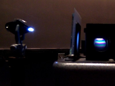
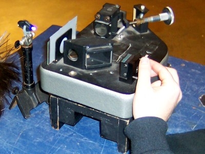
The interferometer assembly is a Beck-Ealing model 25-700 Interferometer . The light source used is a 5 mW HeNe laser mounted on an optics rail with a 30µm pinhole as a beam expander. Beam alignment is described in Setting it Up.
Setting it up:
The interferometer is cart mounted and raised on a wooden block so that the laser, which sits on an optics rail also on the cart, can be the right height for the mirror array. The fringe pattern should be obtained before class because it can take a bit of fiddling. Block one of the light paths (the path to the beam alignment mirror) and adjust the laser in x and y so that the light spot 2 from the other path falls in the center of the frosted screen. Then align the spot from the second path using the mirror screws so that the two spots are coincident. As you make this adjustment, you can tell when the spots are close because you start to see the outer fringes of the Airey disc as a set of horizontal or vertical lines. Now tweak the screws to work in to the center spot. By adjusting the path length mirror, you can cycle through the phases which alternates the dark and bright fringes. The zero order for our interferometer is given as 1.0450 cm on the micrometer screw adjust. 3 A camera will be needed to view the interference pattern; this should also be cart mounted.
Comments:
As well as providing mobility, the wheeled cart plays the role of the mercury bath in Michelson's original experiment, allowing the apparatus to be rotated on its axis by 90°. This demo is not really used for much more than "show and tell."
1 See for example, the Feynman Lectures on Physics volume I (Addison Wesley, 1963)
2 Most easily done without the beam expander
3 At this setting a white light source can be used to show the coherence length; the complementary colors of the spectrum are observed.