We have designed and built our own cosmic ray telescope (a.k.a. spark chamber). Unlike the old one, this one works reliably, is larger, and makes for a great demo.
In the 1960's and '70s, spark chambers were commonly used as detectors in particle physics experiments. They served as visual detectors with moderate spatial resolution (≈ ±0.5 mm) and time resolution (≈ ±0.5 μs). Higher spatial and temporal resolution detectors, such as drift chambers and silicon detectors, have since replaced these. However, the spark chamber is still well suited for lecture demonstration — the detection of cosmic rays (usually muons) can easily be made visible to a large audience. About 80% of the cosmic ray flux at sea level is composed of muons, with electrons and protons making up the remainder.
What it shows:
If a high voltage is suddenly applied to the gap between a pair of parallel plates shortly after an ionizing particle has passed through the inert gas between them, a spark jumps along the path of the particle. If a number of such gaps are stacked vertically and operated simultaneously, the track of the particle is defined by a line of sparks — the line of sparks can be observed directly or buy video projection. Muon tracks, which occur at a rate of about 10 per minute, are readily viewed in a large lecture hall.
How it works:
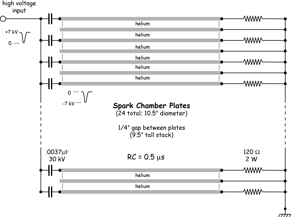
Figures 1 and 2 show schematically how this is accomplished. The spark chamber proper is a stack of 24 plates sandwiched between two plastic scintillation detectors. When a cosmic ray penetrates both scintillators, a fast coincidence signal is produced to indicate that a particle has passed through the apparatus (in a time window of less than a couple of nanoseconds). That signal in turn triggers the high-voltage pulse generator which delivers a 7 kV pulse to alternate plates of the chamber within 1 μs of the trigger.
figure 1: apparatus configuration
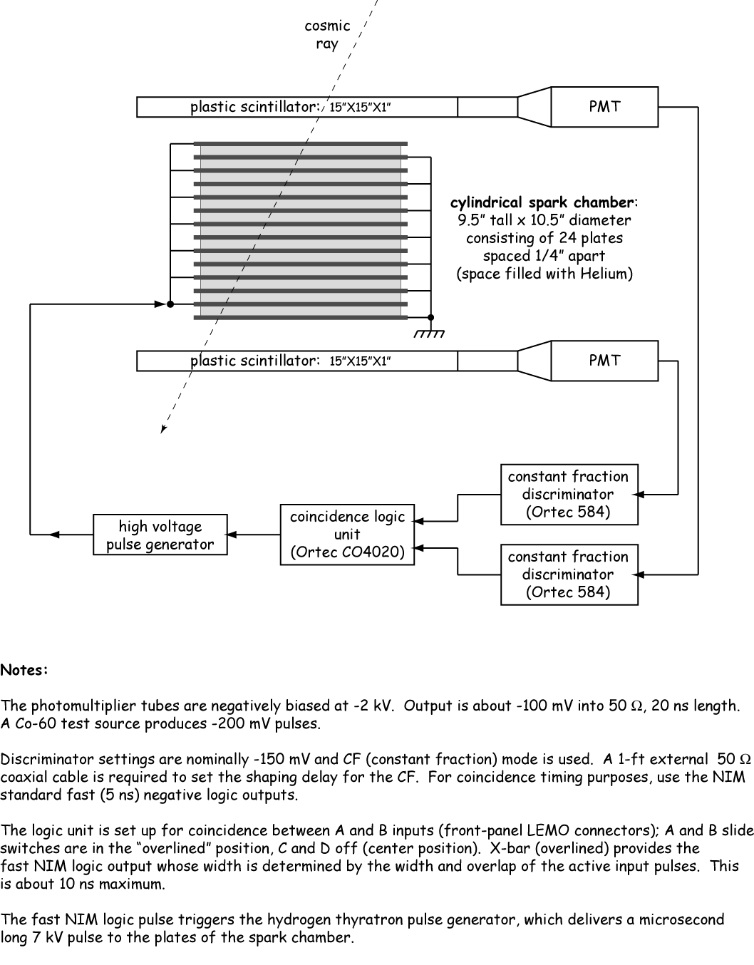
figure 2: electrical connections to the plates
As the muon passes through the stack of plates, it ionizes the gas between them. This trail of ions and electrons becomes the favorable path for the forthcoming spark. The electrons eventually recombine with the ions, the rate of recombination determined by the gas. An electonegative gas such as oxygen recombines rapidly; inert gases recombine more slowly. For this reason, spark chambers employ one of the noble gases. However, even for inert gases, the recombination rate is fast and the high voltage must be applied to the gaps within about ½ μs after the passage of an ionizing particle. (One cannot use a continuous voltage as random sparking would occur between plates.)
Setting it up:
A dedicated cart holds the spark chamber proper, scintillation detectors, NIM bin with discriminator & coincidence modules, and PMT power supplies. A separate full-size relay rack (on wheels) holds the Triggered HV Pulse Generator and all the ancillary power supplies necessary for its operation. Detailed operation procedures, circuit diagrams, and notes can be found in the notebook kept with the apparatus. You will probably need one of our demonstrators to help you run this during your lecture.
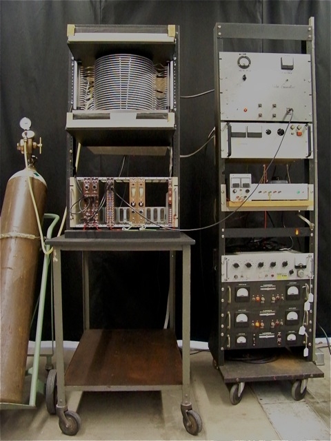
front view of entire apparatus
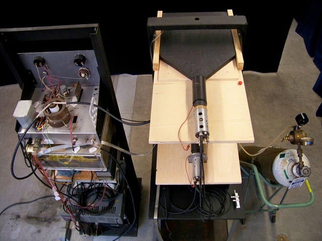
Top view of apparatus showing "paddle" scintillation detectors between which the spark chamber is sandwiched.
Comments:
A dramatic (and not often seen) demonstration of the constant rain of cosmic rays penetrating through us all the time. A good companion demo would be the cloud chamber.
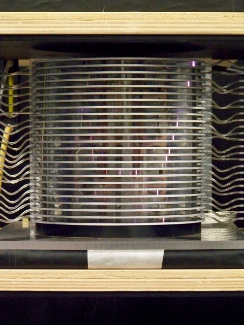
Preliminary test of spark chamber at low voltage. Helium gas flows in from the left and exits on the right at a rate of about 1 CFH.
Muons are the product of very high energy (108 to 1020 eV) protons and light nuclei that collide with molecules in the Earth's upper atmosphere. Interactions between protons and atmospheric nitrogen or oxygen nuclei yield secondary particles, which include pions and kaons (both mesons). Both of these have a lifetime of the order of 10-8 second and decay into muons. Muons are also unstable and decay into electrons and neutrinos. Relativistic effects allow some to reach the Earth's surface. The muon flux rate on the Earth's surface is commonly cited as 100 muons/m2·sr/second. The stack of plates subtends 0.86 sr of solid angle and, with an area of about 0.05 m2, one would expect around 250 events per minute. We limit the number of events with judicious use of the discriminators.
For further information on the muon, see the Physics 191 Adv Lab notes Mean Lifetime of Muons in Matter. The spark chamber and hydrogen thyratron high-voltage pulse generator are our own design and construction — circuit diagrams are available upon request. The coincidence logic electronics is commercial fast NIM-bin instrumentation.
References:
B. Brau, C. May, R. Ormond, and J. Essick, "Determining the muon mass in an instructional laboratory," Am J Phys 78 (1), 64-70 (2010). The authors use a multi-plate spark chamber to observe the muons and decay products.
W.P Trower, "Resource Letter PD-1 on Particle Detectors," Am J Phys 38 (7), 795-805 (1970)
Bubble and Spark Chambers, Vol 1, edited by R.P. Shutt, (Academic Press, 1967), Chapt VI: "Spark Chambers" by J.W. Cronin
D. Grossman, Theory and Operation of Wide Gap Spark Chamber, Harvard Physics Department PhD Thesis (1967), appendix II — Technology of High Voltage Impulse Generators, pp 160-197; available in Physics Research Library
A.M. Sachs, "Spark Chambers: A Simplified System for the Observation of Particle Trajectories in Two Types of Chamber," Am J Phys 35 (7), 582-594 (1967)
J. Earl, "Spark Chamber for Cosmic-Ray Demonstrations," Am J Phys 31, 571-574 (1963); This is also written up in Meiners, Physics Demonstration Experiments, vol II, 1272-1274; construction 1390-1392; principle of 1290.
G.K. O'Neill, "The Spark Chamber," Scientific American 207, 36-43 (August 1962)

