What it shows:
The transmission and detection of radio frequency electromagnetic radiation by use of LC oscillator circuits recreates the discovery by Hertz of a method to generate and detect electromagnetic waves.
How it works:
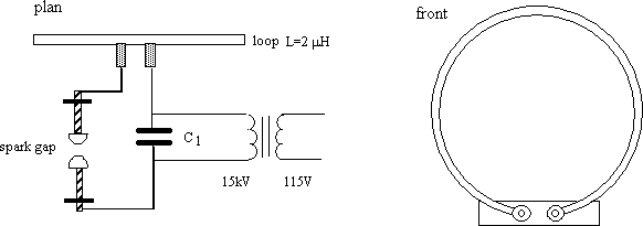
The core of the apparatus (figure 1) is a series LRC circuit (the R provided by the circuit resistance). The inductor L is a 1m diameter loop made of 1 inch copper tubing which also serves as the radiating antenna. A transformer 1 supplies 15kV to charge up the capacitor 2 until the breakdown voltage of the air between the spark gap is reached. At breakdown, a spark completes the LC circuit which oscillates at its resonant frequency ϛ given by![]()
For L=2 μH and C1=1.28 nF the oscillating frequency is 3 MHz. During each oscillating cycle, a percentage of the electrical energy (around 15-20% 3 ) is radiated as RF by the loop antenna so the oscillations die off after five or six cycles. Of course, the spark gap discharge is occurring with a frequency of 120 Hz, fast enough to appear continuous to our eye but much slower than the decay time of the LC oscillations.
Figure 1. Oscillator / radiator circuit
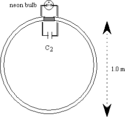
The detector (figure 2) is a tuned receiver with the same resonant frequency as the transmitter. It too consists of 1m copper loop, a series capacitor C2=1.28nF and neon bulb. 4 Because the neon conducts when the potential across the cap is 60V, there's no need for a high voltage cap in the receiver. At a distance of up to few meters, the detector circuit will ring and the bulb will light. Although this is the range limit for a bulb detector, a CRO in its place will detect the RF signal across the lecture hall.
Figure 2. Receiver / detector circuit
Setting it up:
The transmitter has a dedicated (waist height) wooden cart, with the components laid out pretty much as in the figure. The detector loop is hand-held—be careful where it is placed when not in use; the bulb is exposed and fragile (as we've found out!).
Caution: Be very careful not to touch the exposed LETHAL 15kV of the transmitting coil antenna!
Comments:
A variation on the original experiments performed by Heinrich Hertz between 1886 and 1891 to transmit and detect radio frequency electromagnetic radiation. Hertz's original apparatus used a dipole E field antenna as transmitter and square loop receiver with spark gap instead of the neon bulb. Here our transmitter is a loop B field antenna. Since we are very much in the near-field of the transmitting coil, what the receiving coil picks up is more likely due to Faraday induction than electromagnetic waves. The main purpose of the apparatus is to demonstrate the concepts behind production, transmission, and receiving of electromagnetic waves and not that we are actually experimenting with electromagnetic waves. A magnificent setup just to light a puny neon bulb, but the spark discharge makes up for it!
References:
H. Hertz, Electric Waves, translation by D. E. Jones, Dover Publications, New York, 1962
J. H. Bryant, Heinrich Hertz: The Beginning of Microwaves, IEEE Service Center, Piscataway NJ 08854, 1988
1 Jefferson Electric Company Luminous Tube Transformer (Bellwood, Ill.)
2 2 x Sprague (6626) 3900mmF 30kV capacitors in series
3 A value quoted for a Hertzian dipole antenna; we haven't the data for a loop antenna.
4 Bulb is, was, a GE type R1A